Connecting up the MCP23S17 and HD44780U based LCD
read
HELP SUPPORT MY WORK: If you're feeling flush then please stop by Patreon Or you can make a one off donation via ko-fi
In my Raspberry Pi starter kit I also got a LCD display based compatible with the Hitachi HD44780U controller.
WiringPi has some nice simple support for this.
The LCD supports being driven in 8 bit mode (which requires 10 GPIO pins) and 4 bit mode (which required 6 GPIO pins). Although you can use all 17 GPIO pins for your own purposes I want to keep the I2C, UART and SPI functionality free for further projects, which means I only really have 8 pins to play with. I also want to connect up my 1 wire temperature sensor and later on my infrared sensor. This means that even using the LCD in 4 bit mode I’m going to be running out of pins.
Fortunately the GPIO is quite extensible using the I2C or SPI pins. The simplest way to do this is to use the MCP23S17 which is supported by WiringPi.
The Pi has 4 pins supporting SPI:
- CEO, CE1 - chip select pins
- SCLCK - Clock
- MISO - Master in, slave out
- MOSI - Master out, slave in
Connecting the MCP23S17 is simply a case of connecting these pins up.
- PIN 11 (CS) -> CE0 (or CE1)
- PIN 12 (SCK) -> SCLCK
- PIN 14 (SO) -> MISO
- PIN 13 (SI) -> MOSO
- PIN 9 (VSS) -> 3v
- PIN 10 (VDD) -> GND
- PIN 15-17 (A0-A2) -> GND - This sets the address of our chip to ‘0’
- PINT 18 (_RESET) -> 3V - Don’t forget this like I did - you’ll be scratching your head for a while…
You can then connect whatever you want to pint 21-28 and 1-8.
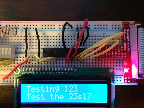
Connecting up the LCD display should be straightforward. I was fortunate that the pins on my connector married up really nicely with the pins on the MCP23S17 as shown here:
A and K (Anode and Cathode) for the back-light are connected the VSS and VDD pins - I’m able to do that with my module because it has a built in resistor - you should check your module first!
The data pins for the LCD match up with pins 1-8 on the MCP23S17. I’m going to use the LCD in 4 bit mode so I can use a couple of these pins to drive the E and RS connections on the LCD.
If your LCD module is 5v, make sure you tie the RW pin to ground.
VSS is connected to 5v and VDD is connected to GND.
V0 controls the contrast - initially I had this wired up to a 10K pot, but once I’d found a good setting I replaced that with two resistors dividing +5 and GND.
That’s it for the wiring up. To make it do something we have to install wiringPi and write some simple code.
#include <stdio.h>
#include <wiringPi.h>
#include <mcp23s17.h>
#include <lcd.h>

#define BASE    100

int main (void)
{
        wiringPiSetup () ;
        mcp23s17Setup (BASE, 0, 0) ;
        int fd = lcdInit(2, 16, 4, BASE + 10, BASE + 11, BASE + 12, BASE + 13, BASE + 14, BASE + 15, 0, 0, 0, 0);

        lcdHome (fd);
        lcdClear (fd);

        lcdPuts(fd, "Testing 123");
        lcdPosition(fd, 0, 1);
        lcdPuts(fd, "Test the 23s17");
}
The first step is to initialise wiringPi. We then need to initialise the SPI mcp23s17 as shown here. The first number (BASE) is our pin offset, the second number is the SPI port (0 or 1) and the third number is the address/device id.
For the LCD we we give the number of rows, columns and bits (4 or 8) and then list the pins as detailed here.
To compile and run this program you have to link with wiringPi and wiringPiDev and before running you have to load up the spi driver module.
g++ spi.c -L/usr/local/lib -lwiringPi -lwiringPiDev
gpio load spi
sudo ./a.out
With the 3 address lines and two chip selects you could potentially connect up 16 extenders to your Pi giving you 256 IO pins!
Related Posts
Raspberry Pi temperature sensor - In just a bit of time, I managed to successfully get my temperature sensor, the DS18B20, up and running on my new Raspberry Pi. My starter kit even included a ready made circuit board for the sensor, making wiring a no-brainer. After following the setup instructions and inputting a few commands, voilà, my temperature readouts were coming in loud and clear. Ready to tinker around and perhaps even move the connection pin if needed.
Forget SSH and vim, Use VSCode to Remote Develop on the Raspberry Pi - In this blog post, I share how you can avoid hassles of SSH and use VSCode for remotely developing on the Raspberry Pi. I walk through how to initially configure the Pi in a headless setup using the Pi imager app. Then, we install the 'Remote Development' extension in VSCode. I illustrate how easy it is to connect to the Pi using our SSH credentials, clone a GitHub project, and install python extensions. Finally, I explore how to run the code and debug it. However, note that the method doesn't support armv6, so you can't use it on Pi Zero.
ESP32-S3 Hardware SPI on the Adafruit ST7789 - I've had some commenters point out the issue with the slow display updates in my recent Arduino Nano ESP32 video. It turns out, the software SPI of the Adafruit_ST7789 library was the culprit. Lo and behold, the solution is simple - using the hardware SPI constructor of the library. Apparently, this isn't well documented, so I wrote some code to serve as reference for myself and others who might run into the same snags. Trust me, the difference in speed is absolutely bonkers. Check out the video to see the magic in action.
Self Organising WS2811 LEDs - I've successfully used addressable WS2811 LED strings and an ESP-CAM board to create an adjustable lighting system. The best part is that the image processing code can be duplicated in JavaScript which allows you to use a plain dev board to drive the LEDs instead of needing a camera on your ESP32 board. If you want to replicate this project, you'll need your own ESP32 dev board and some addressable LEDs. After figuring out the location of each LED in 2D space, it's easy to map from each LED's x and y location onto a pattern you want to show on the frame buffer. Desiring to keep it accessible, I've posted detailed instructions and my sample code on GitHub, making sure anyone with basic knowledge can undertake this fun technological DIY project!
Raspberry Pi BTLE Device - Just wrapped up the first iOSCon hackathon and had a blast tinkering with my Raspberry Pi, turning it into a full-fledged Bluetooth device in sync with an iPhone app. Used node for setting up and Bleno for creating Bluetooth low energy peripherals. Penned down each step for you to replicate, right from writing strings on my LCD to reading temperatures and getting notified of IR remote button clicks. Ran it on an app store or GitHub test application. Also, explored the Core Bluetooth framework for iOS app creation, for reading and writing data to the Raspberry Pi. Let's keep creating magic with technology!
Related Videos
Live GPIO Viewer - In my latest discovery, I found an incredibly efficient visualization tool from the last outpost workshop that upgrades how I check the status of the GPIO pins on my ESP32. It's super simple to use and allows me to monitor pin activities directly. I set up a couple of LEDs and a button on various GPIO pins to demonstrate its effectiveness and the results were fantastic. Although it currently supports only digital input and output and PWM, I'm optimistic it will expand with time. Thanks to the open-source community, you can find the setup instructions in a GitHub repo. This tool is a revelation and I highly recommend it.
Getting started with Raspberry Pi Pico - MicroPython - Learn how to get started with Raspberry Pi Pico by soldering headers, writing codes, and building a classic blinking LED project in this tutorial.
ESP32-S3 - Which Pins Are Safe To Use? - In this video, I've decided to dive deep into the ESP32-S3, a module ruling my lab recently due to its plug-in-and-play functionality, and the flexibility offered by its GPIO matrix. However, working with it requires vigilance, especially with regard to the strapping pins and USB data pins, among others. Discovering such quirks, I've encountered unexpected values, short glitches and the occasional code crash. To help you avoid these bumps, I've documented everything I've learned on my GitHub repo, where I'm inviting you, my fellow makers and engineers, to contribute your valuable experiences and findings. After a minor hiccup with my ESP32-TV, expect an updated PCB design, courtesy of PCBWay. Explore the ESP32-S3 with me, and let's unravel its secrets together, one pull request at a time.
Magic LEDs: Self-Organizing with ESP32 CAM & Simple Image Processing! - Unleash your creativity and transform chaos into order using an ESP32 camera board, image processing, and a string of WS2811 RGB LEDs. Find out how wiring, level shifting, and a simple web interface bring this mesmerizing project to life.
Giant 7-Segment Display: Journey from Monolithic to Modular! - Learn how a modular PCB design created a four-digit seven-segment display using TPIC6595 power shift registers and SMD components, capable of sinking large currents.
HELP SUPPORT MY WORK: If you're feeling flush then please stop by Patreon Or you can make a one off donation via ko-fi